-
Draw out base with coax numbered clock wise starting at leg closest to north
-
Climbing personal should determine with the help of one person on the ground to verify heights of antenna, type of antenna, azimuth of antenna, leg, coax size, type of mount
-
Combiners/ splitters and tag coax using base numbers, of all coax and antenna.
Numbers at the base of the tower will also give a starting number to chase coax into the building. Use simple numbers on the tower that can be made in advance 1,2,3,4,5 etc
-
Follow each coax to transmitter documenting all combiners/cross band couplers etc. Use form TA-101 (this form can also be used for Intermod-MPE information)
-
Temporarily tagging with corresponding tower number at building ingress/egress, different rooms ingress/egress, combiners etc and then transmitter.
-
Identify and document coax size, make, model, frequency, of all equipment, TX, RX, dummy load, etc Use form TA-101
-
Draw a rendering of room with location of equipment, then assigning a room number, row letter of equipment etc. (example, room 4- row A- position 5 combiner-C-tower coax 15) stat in NW corner of building and then rooms for ID schematics
-
Enter information into Tower Audit spreadsheet at the site. Doing this as you go will insure that all information that is available can be obtained.
-
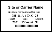
Draw a rendering of each tower coax number as such:

Permanent Tagging of Coax and Equipment Numbering System (If Applicable)
-
FCC structure number (last three digits)
-
Room number of equipment numerically based on drawing of building layout
-
Row of equipment if applicable based on drawing of room layout, (alphabetically)
-
Position of equipment numerically, if in a rack configuration
-
Note if combiner, C cross band coupler CB duplexer D etc
-
Coax number used at the base of tower.
-
Height of antenna on tower
-
Type of antenna
-
Azimuth of antenna
-
Bar Code
